Build your own autopilot
Minimal hardware
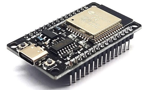
- ESP32 microcontroller - $4
- Motor driver - $7
- 5V power supply (USB) to the ESP32 - $2
- Wires - $2
- An actuator driving your rudder
- Your phone or tablet
Recommended hardware
- Fuse
- A box
Software
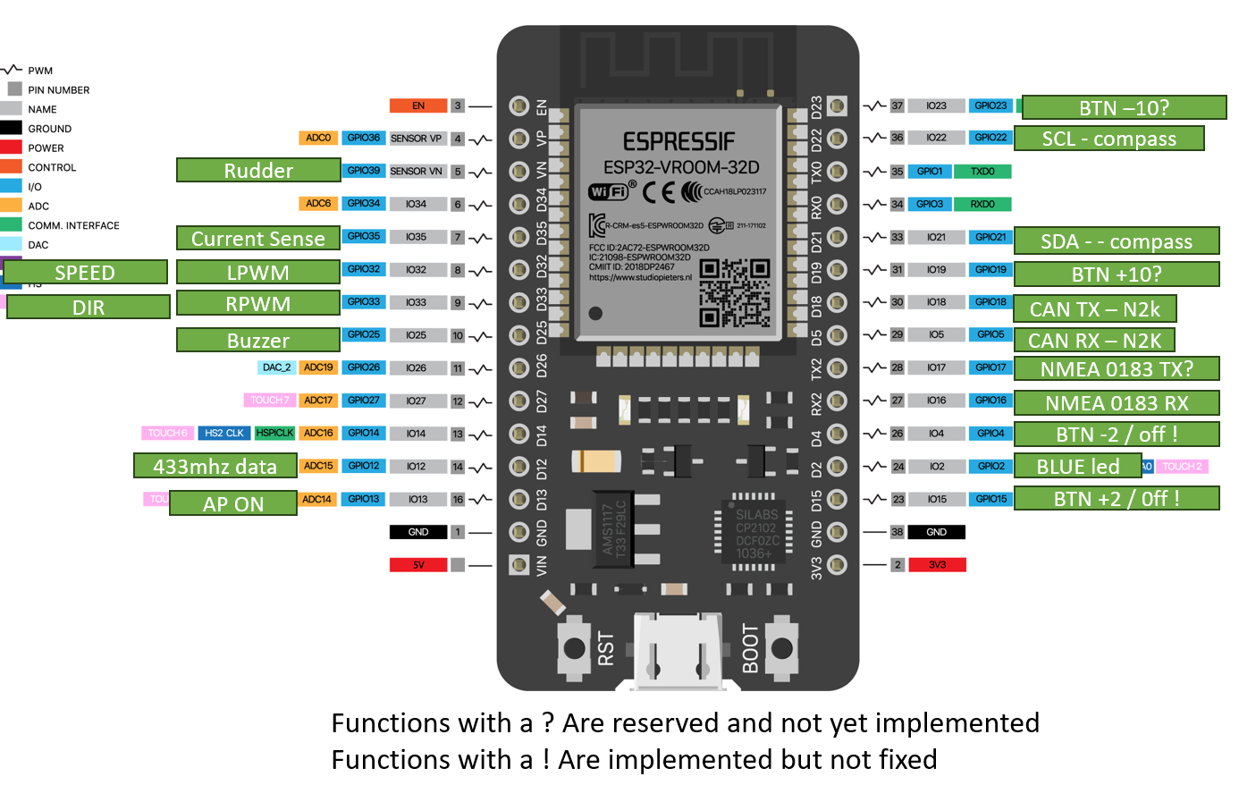
ESP32 Microcontroller
Motor driver
A motor driver translates the PWM signal from the ESP32 into a high switching current to control the motor direction and speed. I use the IBT-2 motor driver for its availability, price, and support for motors up to 43 Amps. Alternatives include the L298N or L293D. The IBT-2 is available on AliExpress: aliexpress.com/item/4000121484634.html, or from local/online suppliers such as Amazon.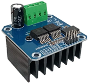
Wires
The wires to connect the ESP32 are called female-to-female jumper wires (Dupont). You need 6 wires to connect the ESP32 to the motor driver, but packs usually include at least 30. The motor driver requires a direct supply from your boat’s battery. Two output wires must be connected to your motor.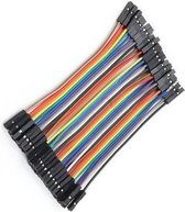
Power supply
You can power the ESP32 via USB or the VIN pin. A good option is an ESP32 expansion board, which converts 12V to 5V and provides easier wiring. Ensure it supports up to 16V and buy an additional DC plug. https://aliexpress.com/item/1005004673048101.html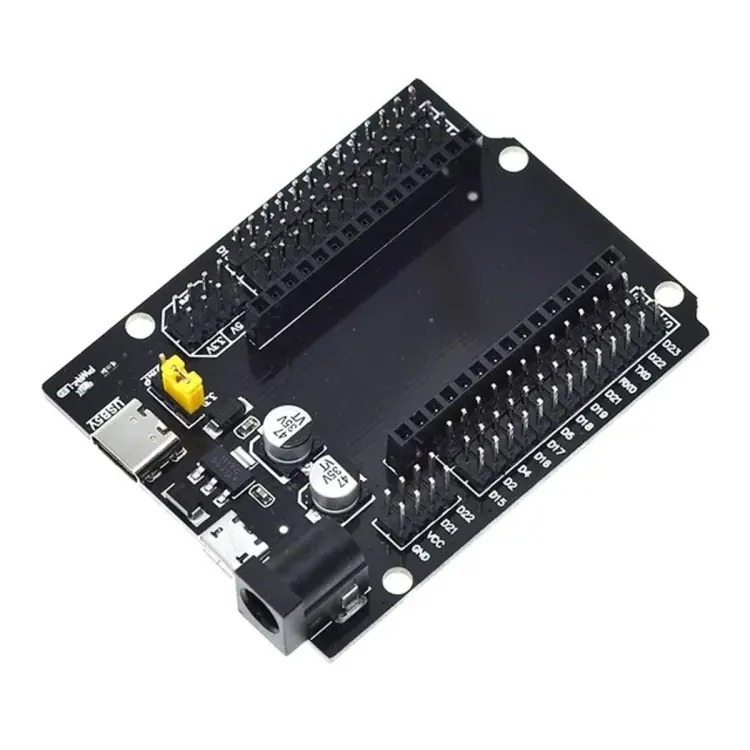
Actuator
The actuator is the motor that drives your rudder. You can use an existing one or buy new. Steering types:Tiller steering
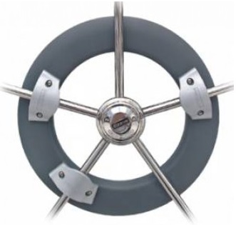
A linear actuator is recommended. Specs: 300mm stroke, 50mm/s speed, 200N force (full left to right in ~10s). Example: https://nl.aliexpress.com/item/1005004205595864.htmlWheel steering
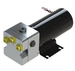
Options include wheel drives from Raymarine or second-hand units. Example: ST4000 wheel drive.Hydraulic
Requires a hydraulic pump (e.g. Hy-Pro 0.8 liter, ~€300). Size the pump displacement to your cylinder volume.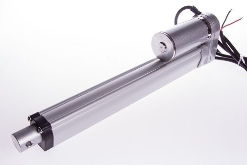
Software installation
- Go to the flasher page and flash the firmware to your ESP32.
- If successful, connect to the ESP32 via Bluetooth using the autopilot app.
- The app will then update the firmware, adding support for the built-in compass, NMEA, and wireless remote. After this, the phone is no longer needed.
Phone or tablet
Any phone/tablet with a compass (magnetometer) works. 95% of devices have one—check via a compass app. Verify your device specs at gsmarena.com.Hardware installation
This section covers wiring the components to the ESP32. For convenience, I use an expansion board.
Wiring the IBT-2 motor driver
The IBT-2 has 8 pins, we use 6:1. VCC → +5V from ESP32
2. GND → GND from ESP32
3. R_IS → Not connected
4. L_IS → Not connected
5. R_EN → +5V from ESP32
6. L_EN → +5V from ESP32
7. R_PWM → GPIO 32 on ESP32
8. L_PWM → GPIO 33 on ESP32
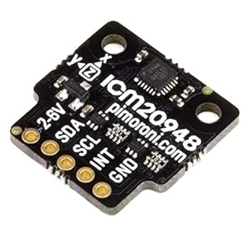
Compass (IMU)
The supported compass is the ICM20948 (9DOF: accelerometer, gyroscope, magnetometer on X/Y/Z). Recommended: Pimoroni module. Since the chip requires 1.8V, use a breakout board (Pimoroni, SparkFun, Adafruit, etc.) with level shifting for ESP32 (3.3V). Wiring:
- VCC → 3.3V
- GND → GND
- SDA → GPIO 21
- SCL → GPIO 22
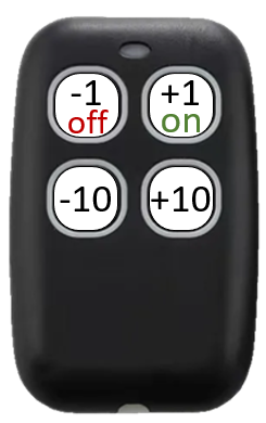
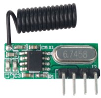
Wireless remote
Requires a 433MHz receiver + remote (must support 3.3V). Wiring:
- VCC → 3.3V
- GND → GND
- D0 → GPIO 12
- 230821 → -1° (manual adjust, AP=on)
- 211124 → -10°
- 880810 → +1°
- 190728 → +10°
Clutch control
The clutch disconnects the actuator from the rudder—useful for engaging/disengaging the autopilot. Hydraulic: usually a bypass valve. Mechanical: electromagnetic clutches. GPIO13 → HIGH when AP is active (use for relay/MOSFET control). Most clutches: 12V/24V two-wire input.
Rudder Sensor
A rudder sensor greatly improves steering precision (~50% fewer corrections). GPIO39 (VN) reads 0–3.3V from a potentiometer or hall sensor. It doesnt matter if your sensor only has a 1 volt range. Configure left/middle/right in the app for calibration. Example sensor: https://www.jovialmarine.com/en/shop/rudder-sensor-5
NMEA2000
Connect a CAN transceiver suitable for 3.3V operations. I personally use the TI SN65HVD 234DR. Wire the CAN RX to GPIO5 and TX to GPIO18. Make sure to set the correct termination resistors on the NMEA2000 network.
NMEA 0183
Use an optocoupler than can handle the baud rate an voltage levels of both the nmea network and the esp32. NMEA0183 typically uses 4800 or 38400 baud rates. Use GPIO16 for receiving NMEA data. Transmitting is currently not supported.